Steven Harrap
Fireworks final
The following text describes some of the groups hurdles, strugles, successess and general comments from the production of the final project. Part of it is taken from Joslynes site, an inital word document we produced and extended by myself. My notes are italicied. It is broken into stages that, roughly, line up to two weeks of development per stage.
1. Interface for "fireworks" - notes for testing/ documentation for tangible interface and development of system.
1.1. Stage 1
The project began as an extension of the the second fireworks project. A core code base had been proved from the result of the second project
Interface to fireworks
interface to similar works
- willow wisp - position only
- Casey Reas - touch screen input
- simon penny - traces
- whole body
the environment
- The walls show what is all around the body. I felt that having a surrounding screen that positions the peice in the real world. It gives the fireworks solidity.
- If a spark moves towards the camera and disappears or reappears on the opposite wall, the illusion of it having passed through the user will occur
- A cloud base was considered as a means of allowing the fireworks to disappear into the distance. At a certain depth from the screen we considered the option of making them disappear thus the vironment was not just a void.
- It is important that the user feels part of the experience
- Would whole body tracking work better because then the person themselves would be recognized, not just the controllers they hold.
Using whole bodies instead of single objects means that a bigger area would be required to make the activity a social one. Initial consideration of this factor led us to designs that would have used a considerable amount of floor space. They would have also cost a fortune. The following design was the original concept and would have cost over $300 dollars in projectors alone.
It would mean instead of one to two inputs per person, there would be potentially many more inputs because every part of the body could be used as input.
types of input
- speed of movement
- position
- size
- size could affect attraction/ repulsion
- an outstretched hand could induce curiosity, while the whole body repells

1.2. Stage 2
At this stage I began my investigations into camera tracking. The following notes indicated what we needed the camera to do and what would might be done with the resulting data.
We had already found a code library called OpenCV from Intel for video capture. It is a well tested peice of software and was easily usable with a minimal learning curve. The biggest hurdle at this point was 'Threads'.
We needed the camera to continue to work while the main program was doing its processing. Waiting for the camera to capture and process a frame would bring the motion to stand still at times. To over come this we needed a threading structure to allow both processes to happen simultaniously. C++ has a very low level threading model which would have taken up a considerable amount of the time just to implement. Thankfully an orgaznisation called boost.org supplies many open source libraries that C++ does not natively support - one of which is a threading library. After some experimentation, hair pulling, screaming and finally victory I was able enable threading and allow both processes work concurently.
- Store control frame - for comparison against - means no need for green screen
- Store previous frame to see what has changed
- Store current frame
- Divide frames into grids ie. 8x8 boxes
This turned out to be easier to implement than suspected. No control frame was required - just the previous frame and the current frame. The difference between the two was what we needed. A better result was found if we used the a frame older than the previous (ie the 4th previous frame). This required that a buffer be enabled that stored all previous frames back to the required frame. The buffer acted as a queue releasing the oldest frame for comparing while storing the newest frame.
To find out where movement is :
-
Compare each section of the current frame to the same section in the control frame
If it is the same- Ignore it
We consider the section to be active
Compare the section to the same section of the previous frame
Calculate the amount it has changed (float 0 - 1)
Return the centre point of this point and the float calculated above
The returning of this information required at least one 'middle-man' code class. Threading creates the situation where two processes may try to read or write to the same peice of mememory simultaneosuly. This would create gargabe data and probably crash the program. To over come this one central 'shared' class was created that the front end (what is presented to Joslynes system) and camera process both take turns in talking to.
These values are used as control points and strengths to influence the paths of the sparks
1.2.1. Using the Information:
To update the direction of each spark
- calculate the pull vector
-
for each control point
- calculate the vector from the spark's current position to the control point
- scale the vector by the strength
- add all the resulting vectors together
- scale the resulting vector down by some large value (testing)
- add the result to the spark's current direction vector
A weak control point has less influence over a strong one on a spark
A distant control point has less influence on a spark that a close one
The magnitude of the pull vector controls the colour, and speed of the spark
Where the final pull vector is extremely small the spark may die
1.2.2. Birth
Exact details through testing
when there is more than a certain number of sparks within a section of the screen
some percentage of those will split into two
their direction will be similar to the original spark
speed will be greater
There will be a predetermined minimum and maximum number of sparks
Unfortunatly birth and death never quite occured in the final product - and only because of time limitations really. The idea was very feasable but establishing a stable and reliable system first was the most important goal.
1.2.3. Mapping 2d input to the 3d space
The camera input will only give x, and y values for control points
To find a z value:
- Each control point maps to the centre of an active section
- The z value will relate to how many active sections neighbour a particular section
0 2 3 2 0 2 0 0 3 0 1 0 2 0 0 0 0 1 0 0 - Active sections are grey, value that will be mapped to z in each section
- Calculating this way means that the sparks will be closest where the system detects presence
- They will be closer to where a whole body covers a large block of the camera's view than to an outstretched arm
The supplying of this information back to Joslyne caused some confusion and constination. I believed that the data should be independent of the structure it is supplied in - that is to say that the control point array is ordered from the the top left down to the botton right. Each n elements respresenting a row from top to botton. Each element contains Z, strength, X and Y with the bottom left hand corner being the origin - so the first element of the origin is not the orgin of the X,Y co-ordinates. To some extent this was even dictated by the camera output who's origin can wander depending on what processes are applied to the captured image.
1.2.4. Other Posibilities
Atmosphere in the space
cloudlike
affected by movement of particles
bright particles illuminate the cloud
blurred when behind/inside the cloud
Some sort of sound mapping
one note per section (control point)
pitch and volume depend on
z value calculated for the section's control point
strength of the section's control point (the amount that has changed since the last frame)
Appon reflection sound would probably bring to a grinding halt or be useless on the presentation night against the background hum - who knows...
Another screen
From lecture and class feedback we where starting to feel that the screen design was not winning to many favours. The requirement of having two projects (let alone one) was making everyone worried about the cost. Some group members had voiced the opinion that screen no longer suited the feel of the work. So a new design was prsented...
1.3. Stage 3
Bens shaders are showing promise. Shaders are method of programing that directly uses the video card for producing visual appearance of the individual fireworks. It's a complicated, but very efficient, method and I have only the vaguest idea of how it is actually implemented.
At this point my major contribution to the project is fairly complete. Joslyne occasionally needs adjustments or bugs to be fixed.
1.4. Stage 4
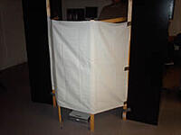
And another screen
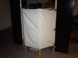
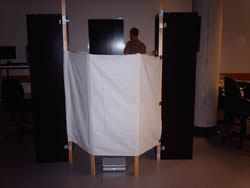
The second screen didn't get much of a response either so a third option has been tabled
This one is even more compact and would cover no more that one square metre of floor space.
Opinons have be voiced that no screen is neccessary and that it should just be projected onto the side of a wall - there seems to be a lack of confidence that we can produce such an item - even after prototyping proves that it could work... oh well.
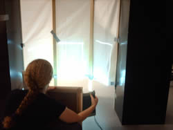
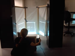
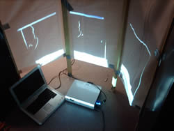
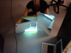
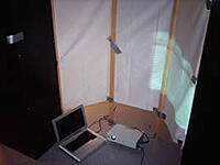
The follow are our experiements with mirrors to reduce the projection distance. From this we grew the idea above.


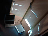
1.5. Stage 5
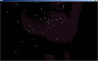
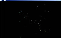
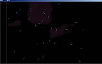
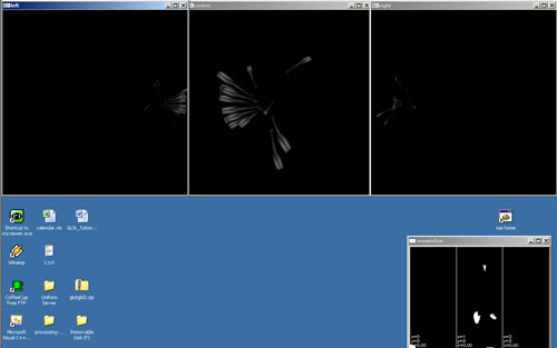
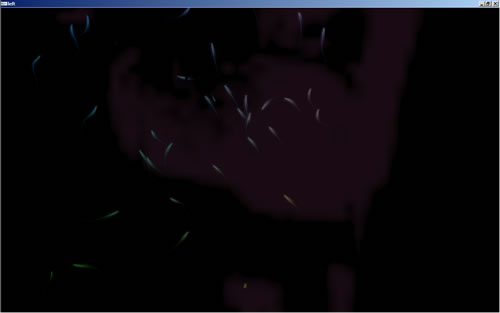
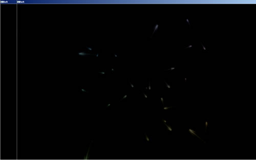
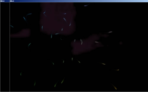
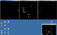
It's nearing completion now. Getting a siloette of the camera input is occuring soon and Bens shaders have improved the look of the fireworks - which are no become more like fishes everyday.
The siloette is just visiable in the last screen shot